Oil passages
Internal fin structures sit inside the oil channels and are enclosed after brazing.
See the internal fin structureBRITISH-STYLE OIL COOLERS
115 mm Matrix · Oil-to-Air Cooler
MATRIX WIDTH
115 mm
Compact matrix for installations with limited width.
MOUNTING · PORT CENTERS · MATRIX
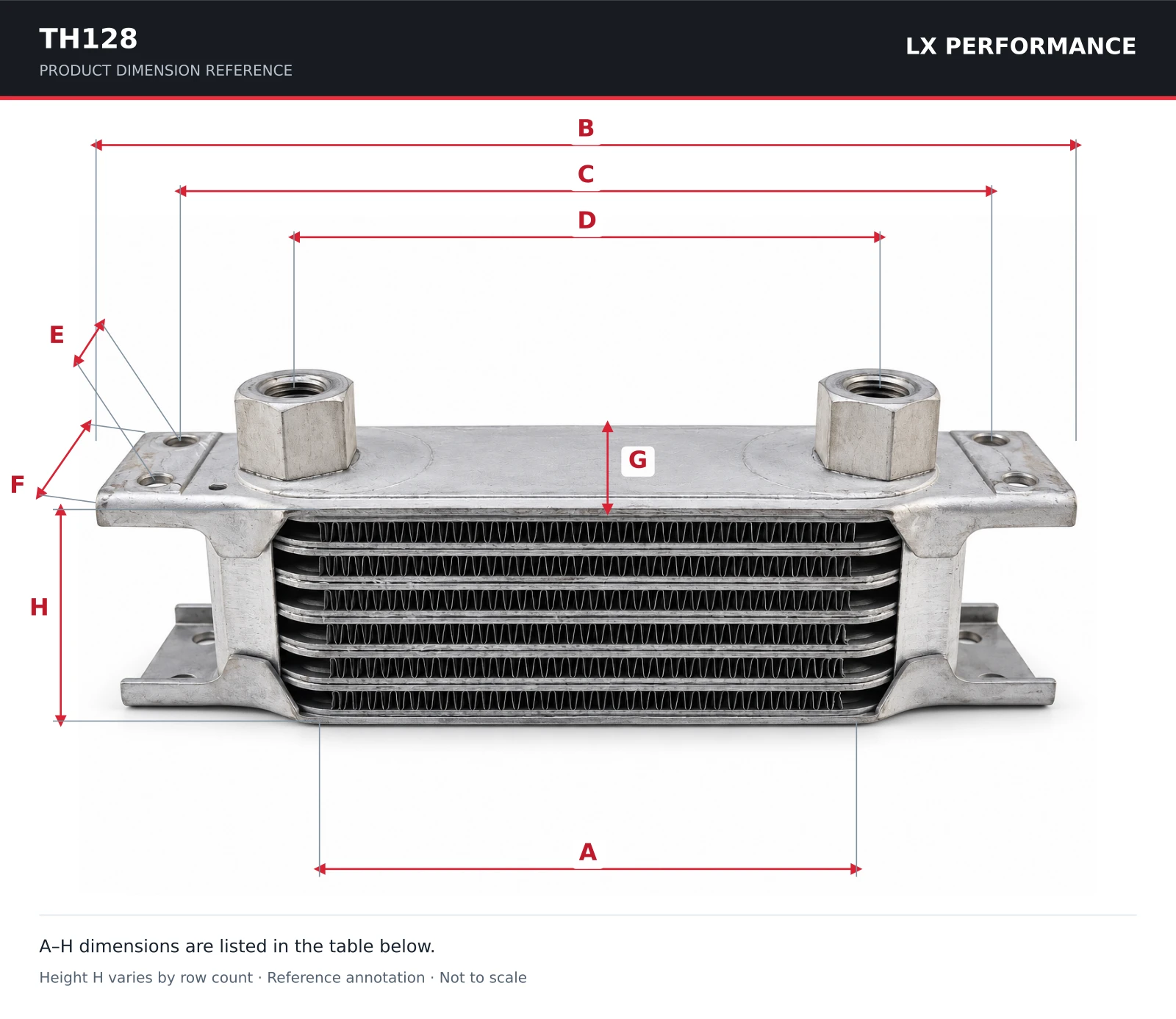
| Reference | Dimension | Value |
|---|---|---|
| A | Matrix width | 115 mm |
| B | Overall bracket width | 210 mm |
| C | Mounting-hole center distance | 188 mm |
| D | Fluid-port center distance | 128 mm |
| E | Mounting-hole center spacing | 22 mm |
| F | Mounting-bracket edge dimension | 41.4 mm |
| G | Matrix depth | 51 mm |
| H | Matrix height | See row-height table below |
H is the matrix height and varies with row count. Dimensions are a reference for the corresponding matrix family; confirm the selected LX production drawing before installation.
ROWS · HEIGHT · CAPACITY · WEIGHT
Matrix width describes the cooling core, rather than the overall mounting width.
| Rows | Core height (mm) | Reference oil capacity (L) | Reference dry weight (kg) |
|---|---|---|---|
| 7 | 53 | 0.08 | 0.31 |
| 10 | 77 | 0.12 | 0.39 |
| 13 | 100 | 0.16 | 0.48 |
| 16 | 124 | 0.19 | 0.60 |
| 19 | 147 | 0.23 | 0.67 |
| 25 | 194 | 0.30 | 0.84 |
| 34 | 265 | 0.41 | 1.15 |
| 44 | 344 | 0.53 | 1.46 |
| 50 | 390 | 0.60 | 1.63 |
| 60 | 460 | — | — |
Capacity and dry weight are Mocal standard-range reference values for the corresponding matrix family. Final LX product dimensions, capacity, weight and available row options are confirmed with the quotation. “—” means the reference table does not list a standard-range value.
Source: Mocal oil cooler dimensions.
Internal fin structures sit inside the oil channels and are enclosed after brazing.
See the internal fin structureCorrugated, louvered aluminum fins form the airflow passages between the oil plates.
See fin and brazing detailsSend the selected row count, installation space, mounting requirements and quantity.
Choose a row-height reference, then request the production drawing and final specification for your installation.
Request TH128OIL COOLER · INTERNAL STRUCTURE
Internal oil fins before assembly and inside a cut-open brazed core.
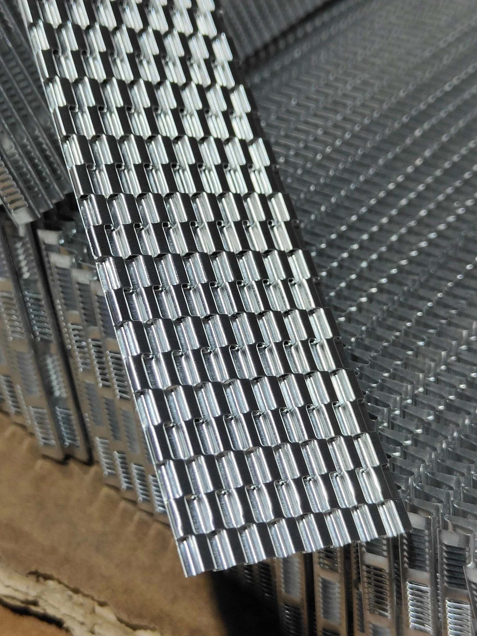
This fin structure sits inside the oil passage. The photograph shows the internal component while it is exposed during manufacturing.
In the finished brazed cooler, this structure is enclosed inside the oil channel and cannot be seen from the outside.
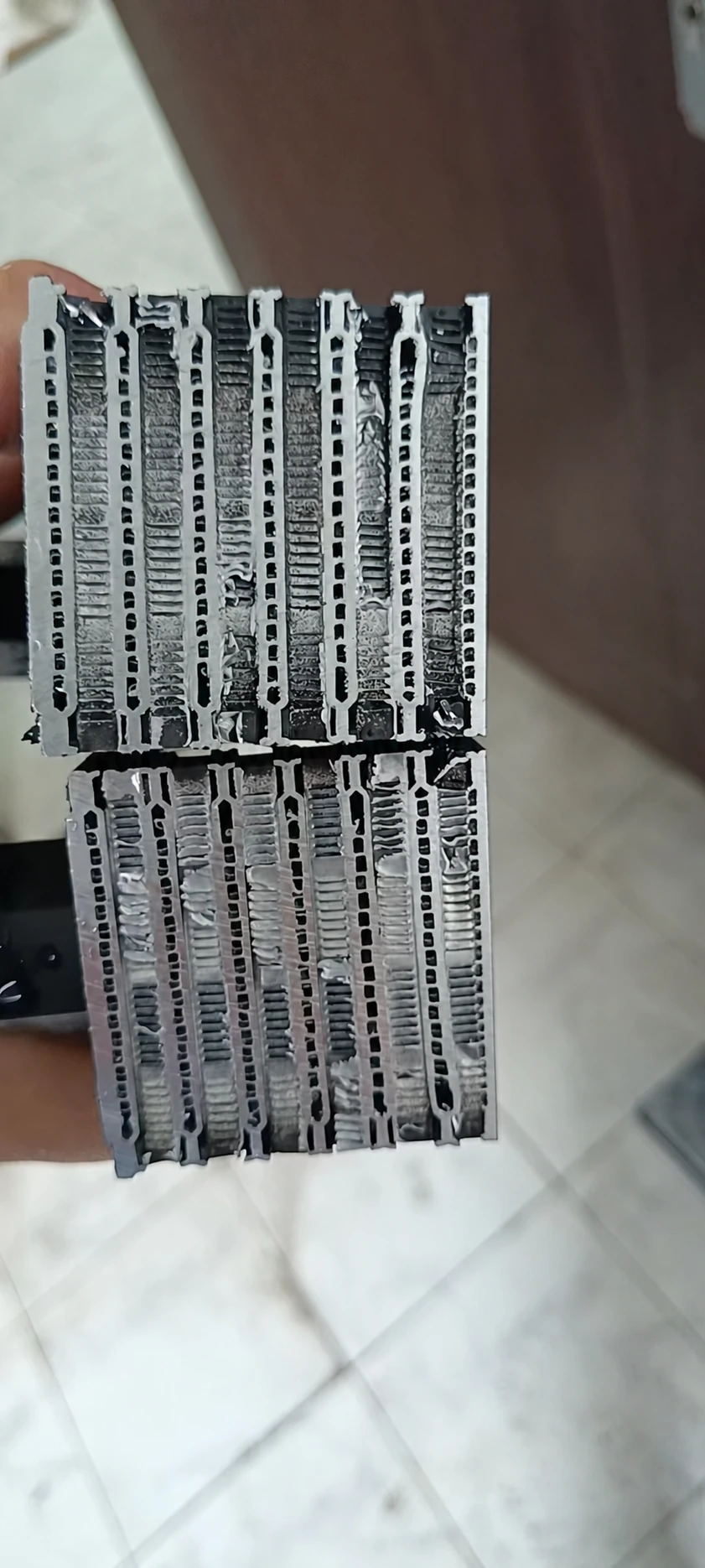
This photograph shows an actual oil cooler core that has been cut open. The fin structure at the center of each narrow channel is the oil passage fin.
These internal fins are enclosed inside the oil passages after brazing. The cutaway reveals the structure that cannot be seen from outside an intact finished cooler.
Factory footage of the equipment and forming tooling used to produce the internal oil-passage fin.
This component sits inside the oil channel. After brazing, it is enclosed and cannot be seen from outside the finished cooler.
OIL COOLER · AIR-SIDE DETAILS
Louvered fins, from formed material to the brazed core. Explore the openings in our manufacturing close-ups.
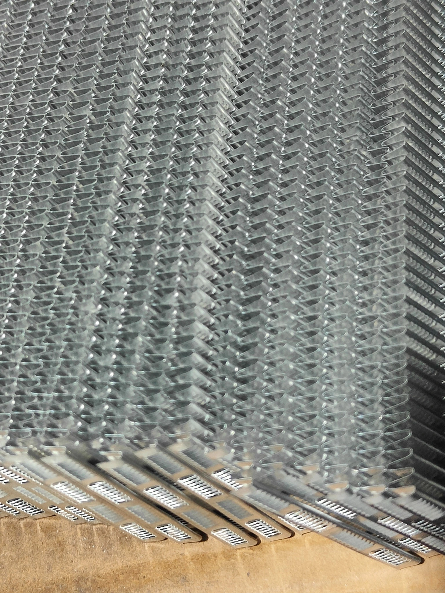
Formed aluminum fins with louver openings.
View full-size photoThe folded fin surfaces contain rows of louver cuts. The close-ups below show these details before and after brazing.
Red outlines highlight the louver openings in the brazed core.
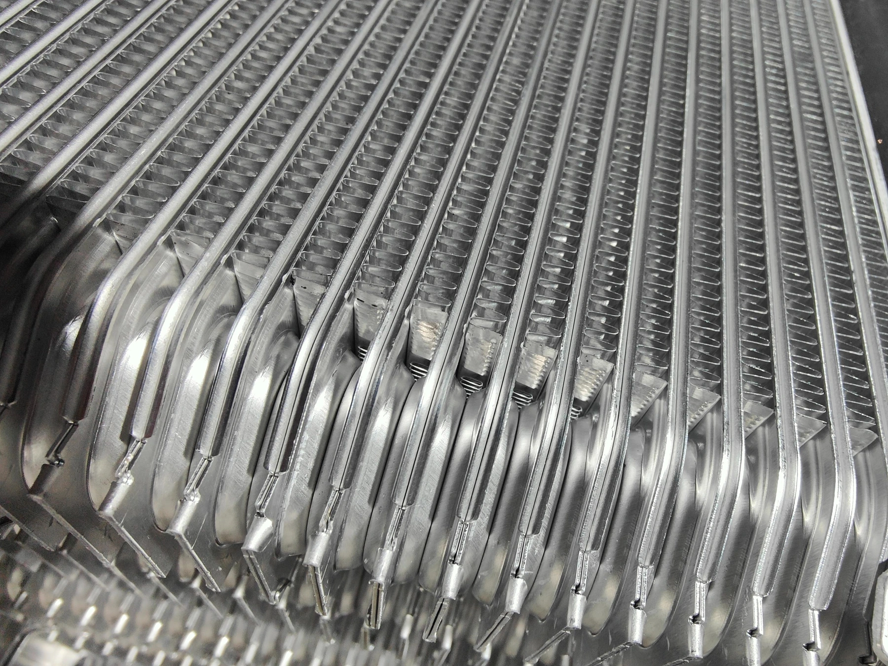
External air passages in the assembled core before brazing.
View full-size photo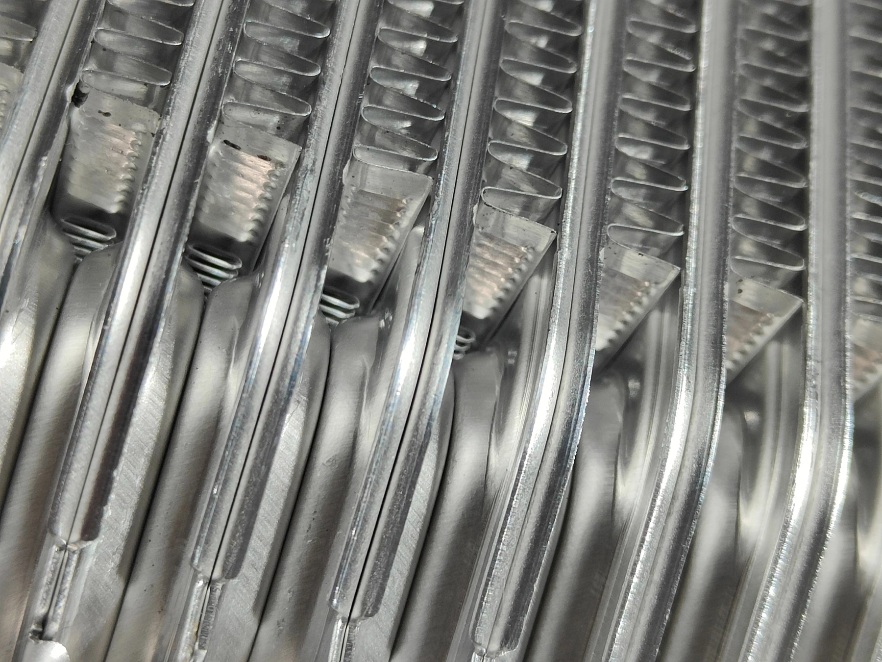
Closer view of the fin folds and louver cuts before brazing.
View full-size photo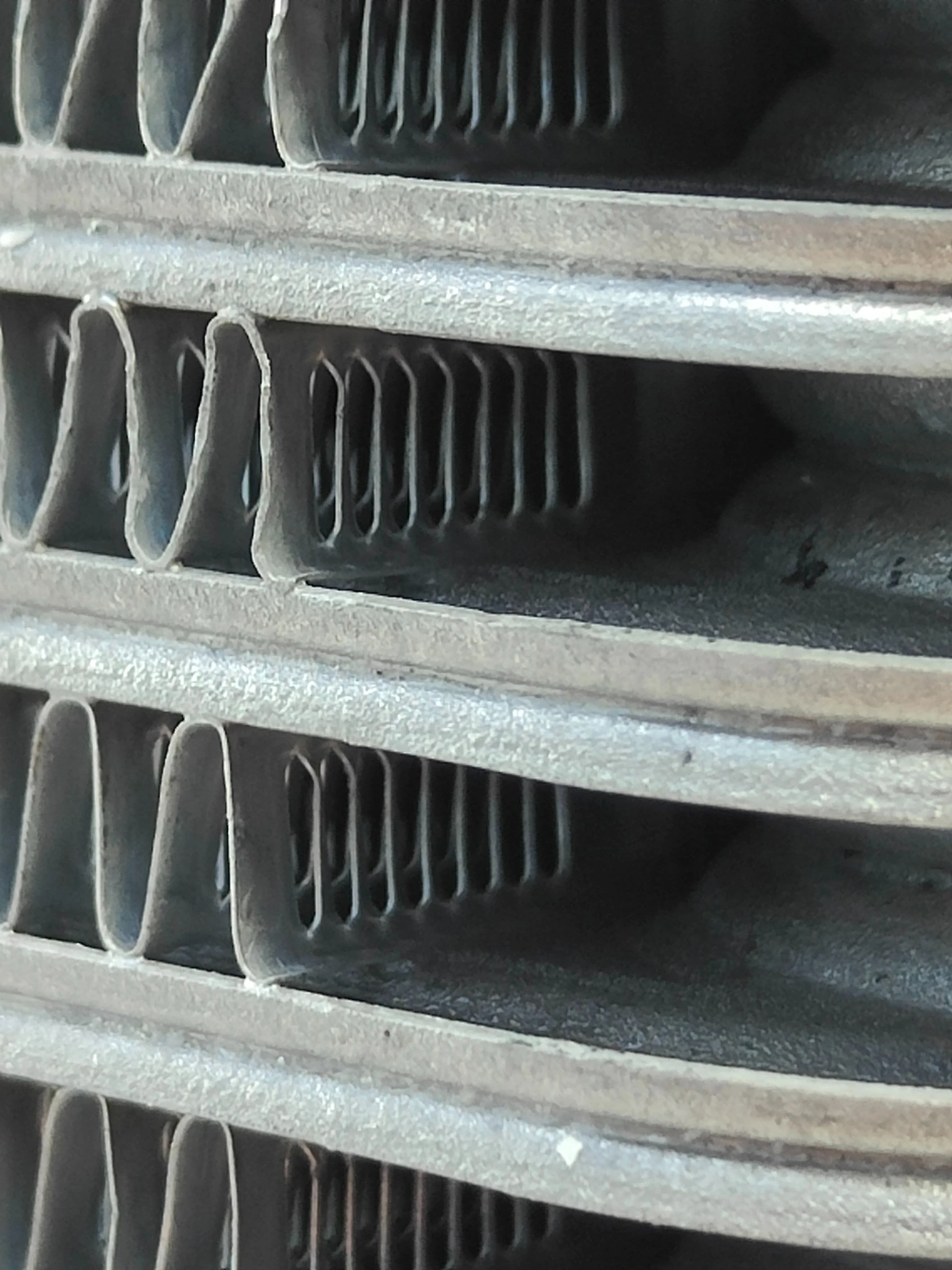 Louver openings
Close-up of the open louver geometry in the brazed air passage.
View full-size photo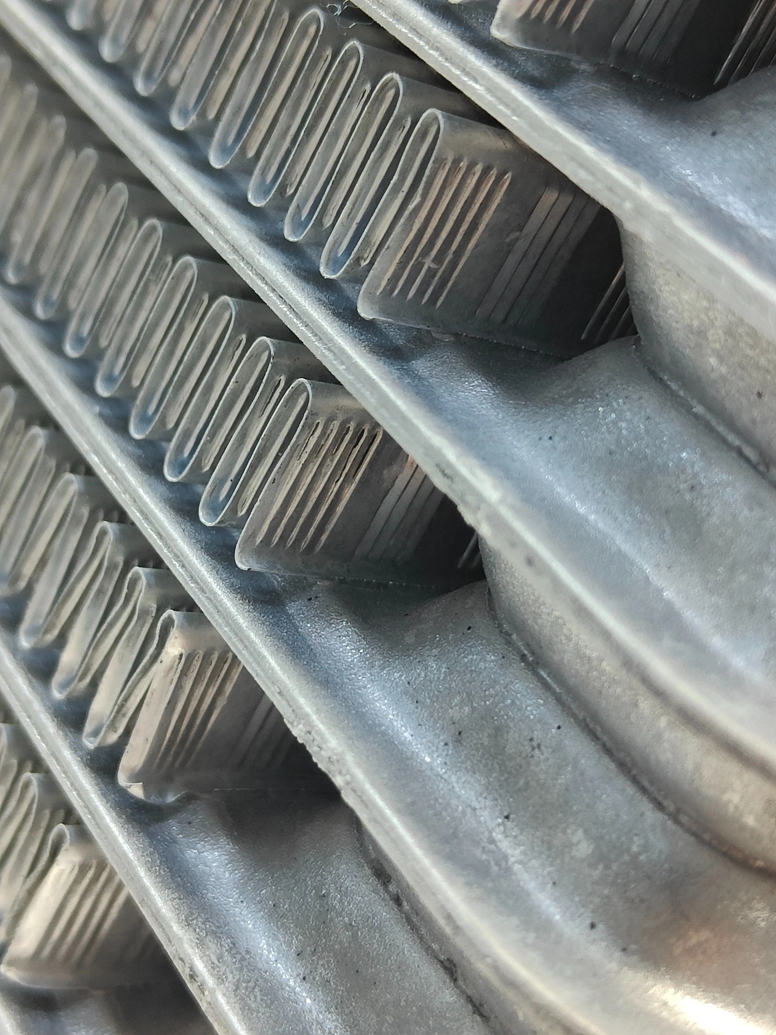 Louver openings
Angled view of the louver openings and surrounding fin surfaces.
View full-size photo